
A cotter joint is a mechanical joint used to connect two coaxial rods and transmit tensile or compressive load from one rod to the other. The connection is made by inserting a flat wedge-shaped piece called a cotter into matching slots provided in the connected members.
Unlike a screwed connection, the cotter joint does not depend on threads for transmitting the axial load. The cotter provides the mechanical locking between the two rods and prevents them from separating during operation.
Cotter joints are generally used where two rods need to be connected in a straight line and the joint may need to be dismantled for maintenance or replacement.
The cotter is usually made from a suitable steel having sufficient strength to withstand the shear and bearing stresses produced during operation. The rod, socket, and spigot are also selected from suitable structural or machine-grade materials according to the application.
The material grade should be selected based on the required strength, working conditions, manufacturing requirements, and applicable material specification.
Cotter Joint Design
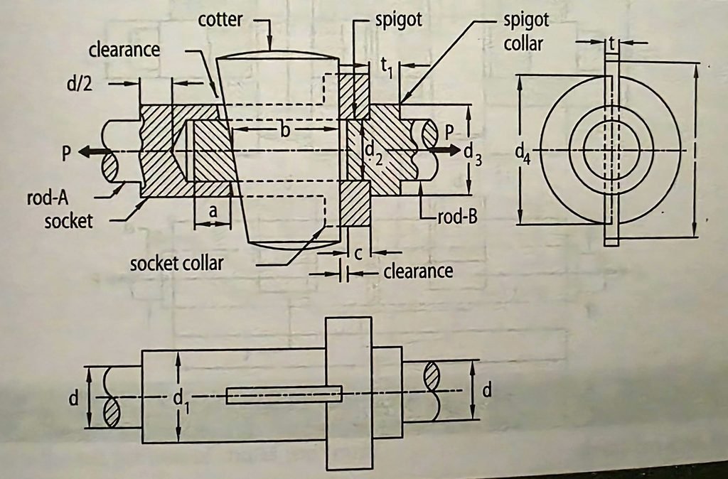
Standard Notations of Cotter Joint
- d = Diameter of each rod (mm)
- d₁ = Outside diameter of socket (mm)
- d₂ = Diameter of spigot or inside diameter of socket (mm)
- d₃ = Diameter of spigot-collar (mm)
- d₄ = Diameter of socket-collar (mm)
- a = Distance from end of slot to the end of spigot on Rod-B (mm)
- b = Mean width of cotter (mm)
- c = Axial distance from slot to end of socket collar (mm)
- t = Thickness of cotter (mm)
- t₁ = Thickness of spigot-collar (mm)
Cotter Joint Main Parts
The basic arrangement shown in the above a design consists of the following main parts.
1. Rod-A
Rod-A is one of the two rods being connected. Its end is enlarged to form a socket, which receives the spigot of Rod-B.
2. Rod-B
Rod-B is the second rod. Its end is formed as a spigot that fits inside the socket of Rod-A. The socket and spigot arrangement keeps the two rods aligned while the joint is assembled.
3. Socket
The socket is the enlarged portion provided at the end of one rod. It has a slot through which the cotter is inserted. The socket surrounds the spigot and provides the supporting surfaces required for transferring the load through the joint.
4. Spigot
The spigot is the reduced or projecting end of the other rod. It fits inside the socket. A slot is provided through the spigot so that the cotter can pass through the socket and spigot together.
5. Cotter
The cotter is a flat, wedge-shaped metal piece inserted through the slots in the socket and spigot. Its main purpose is to lock the two rods together. Because the cotter is slightly tapered, it can be driven into position and can also be removed when the joint needs to be dismantled.
6. Spigot Collar
The above desing also shows a spigot collar. The collar forms part of the spigot arrangement and provides a supporting surface within the joint. It also helps maintain the required position of the connected parts during assembly and operation.
7. Clearance
Small clearances are provided at the required locations so that the parts can be assembled and the cotter can be inserted and removed without interference. Suitable clearance is provided at the required locations to allow proper assembly and removal of the cotter without interference.
How Does a Cotter Joint Work?
The working of a cotter joint can be understood by following the load path through the connected parts. When an axial load P is applied to the rods, the load is transferred from one rod to the other through the socket, spigot, and cotter arrangement.
When the rods are subjected to a tensile load, they tend to move away from each other. The cotter prevents the spigot from moving out of the socket and keeps the two rods connected under the applied load, thereby keeping the two rods connected.
During operation, forces act on the contact surfaces of the cotter, spigot, socket, and rods. These parts must therefore have sufficient strength to withstand the stresses produced by the applied load.
The cotter is usually made with a slight taper. This helps during assembly because the cotter can be driven into the slot to make the connection tight.
Why Is a Cotter Tapered?
A cotter is generally provided with a slight taper instead of being completely parallel. This taper gives the joint a wedge action when the cotter is driven into its slot.
As the cotter moves into the slot, it brings the connected parts into a tight position and helps prevent unwanted movement during operation. The tapered shape also allows the cotter to be driven out when the joint needs to be dismantled.
Therefore, the taper provides two main benefits:
- Creates a tight connection during assembly
- Allows easier removal during dismantling
What Load Does a Cotter Joint Carry?
A cotter joint is mainly used to connect two rods and transmit an axial load along their common axis. Depending on the application, the load acting on the joint may be either:
- Tensile load
- Compressive load
Unlike a shaft coupling, which is used to transmit torque between rotating shafts, a cotter joint is intended for axial loading of connected rods.
For a safe design, the main parts of the joint, including the rod, cotter, socket, and spigot, should be checked for the stresses produced by the applied load.
Stresses in a Cotter Joint
The joint contains several components, so failure can occur in different ways. Important checks include:
1. Tensile Stress in the Rod
The rod has a reduced cross-sectional area around the cotter slot. This reduction can increase the tensile stress in that region. Therefore, the rod must be checked for tensile failure at the weakest section.
2. Shear Stress in the Cotter
The applied load acts on the cotter through the connected members. The cotter can therefore be subjected to shear stress. The thickness and width of the cotter must be sufficient to safely carry the load.
3. Crushing Stress
The contact surfaces between the cotter and the socket or spigot can experience bearing or crushing stress. If the contact area is insufficient, excessive local pressure can deform the components.
4. Shear Failure of the Spigot
The spigot contains a slot for the cotter. This reduces its effective cross-sectional area and creates possible shear planes around the slot. The spigot therefore needs to be checked for shear failure.
5. Failure of the Socket
The socket surrounds the spigot and contains the cotter slot. The remaining material around the slot must be strong enough to resist the applied load. The socket may be checked for tensile, shear, and crushing stresses depending on the design arrangement.
Advantages
- It provides a strong mechanical connection for axial loads.
- The joint can be dismantled when required.
- It does not require threaded portions for the main connection.
- The construction is relatively simple.
- It is suitable for connecting coaxial rods.
Limitations
- The cotter slot reduces the effective area of the rod.
- Stress concentration can occur around the slot.
- The joint is mainly intended for axial loading.
- Accurate fitting of the cotter is important.
- Excessive clearance can lead to looseness and undesirable movement.
Applications of Cotter Joints
Cotter joints are used in mechanical arrangements where two rods need to be connected and the connection has to transmit an axial force. Typical examples include,
- Piston rod connections
- Pump rod connections
- Connecting rods
- Foundation and structural tie arrangements
- Mechanical linkages
- Rod assemblies subjected to axial loading
The actual application depends on the load, dimensions, material, operating conditions, and design requirements.
Types of Cotter Joint
Cotter joints are generally classified according to the way the connected rods and cotter are arranged. The commonly discussed forms include:
1. Socket and Spigot Cotter Joint : The end of one rod forms a socket and the other rod forms a spigot. The cotter passes through slots in both parts to lock them together.
2. Sleeve and Cotter Joint : The two rod ends are connected using a sleeve, with a cotter used to secure the connection.
3. Gib and Cotter Joint : A gib is used along with the cotter to provide a more secure connection in certain arrangements.
These are the commonly used cotter joint arrangements; other modified designs can also be developed according to the application, load, space, and manufacturing requirements.
Conclusion
A cotter joint provides a simple method of connecting two coaxial rods and transmitting axial loads between them. The socket, spigot, and cotter form the main parts of the connection and work together to keep the rods securely joined.
During design, the main components should be checked for the possible tensile, shear, and crushing stresses caused by the applied load. The dimensions of the joint should be selected according to the load, material, and required design conditions.